


LESSON OVERVIEW
In this lesson, we will learn the basics of materials in Unreal Engine. We will tackle how to make reusable materials and material instances, use different types of input data, and cover essential nodes for material creation. The goal is to have a good understanding by the end of this lesson to create basic materials for Environment Artists.
In a previous lesson (WE NEED A LINK HERE), we learned what materials are and how to make a very simple material for a static mesh.
A material is what defines how a surface looks when lit by a light source. It’s a set of instructions that tells the engine how the object should react to light: it’s color, shininess, microdetails, reflection, transparency, and more.
Within Environment Art, material creation is a focused area that often intersects with Tech Art. In some companies, Environment Artists plans and create materials, in others, material creation is a task for a Tech Artist or a collaborative process between the two areas. In general, Tech Artists have a deeper knowledge about optimization, math and code, while Environment Artists have a better hands-on understanding of what they need from a material to achieve the looks and flexibility they want. All of these needs are important to consider when building a material setup that remains clean, organized, flexible, performant, and of course, visually good looking. Materials also help define the texturing pipeline of a project’s 3D assets.
Under the hood, every material in Unreal compiles down into HLSL (High-Level Shader Language) code. This HLSL is plugged into Unreal’s rendering pipeline, which controls how the GPU shades pixels on a screen.
By default, Unreal provides a standard PBR (Physically Based Rendering) shader. It follows industry-standard models for Base Color, Metallic, Roughness, Normal maps, etc. All of these are inputs into the engine’s core lighting model, which is defined in the engine source code (and not editable in the Material Editor).
In this lesson, we’ll go deeper, exploring the main tools we have at our disposal to build flexible and performant materials. Before we start, there are a few things we need to consider when planning our approach to material creation.
What kind of project am I working on?
Depending on what kind of project you’re working on, the needs and effort put on developing materials will vary. To better illustrate this, let’s look at how material needs vary across different types of projects.
Professional/commercial game: The specific needs of art direction and technical constraints are very important here. What kind of looks is the game trying to achieve? What are the technical and hardware limitations? What tools and functionality does the art team need? Expect multiple discussions with people from different teams until most questions are answered and the main needs are laid out.

Hobbyist game: non-commercial, hobbyist, or student projects usually have more flexibility and can often waive a few of the concerns that commercial productions have. It’s less important to be very thorough with the pipeline, although if the people involved have the capacity to do so, it’s always a win.
Portfolio scene: With standalone portfolio scenes, there is one main concern: what do you want to showcase? If the answer is just a good looking environment, your main concern will be making materials that can get you the best looking result, while optimization and efficiency concerns might be an afterthought, pushed to the sidelines. It’s a valid approach, although it’s always best to do it right if you can. However, if you also want to showcase your technical knowledge and thought process about your material pipeline, displaying a clean, efficient, performant and flexible material can be a great way to strengthen your portfolio piece breakdown. Such skills are highly regarded by employers, whether you’re just starting out or looking to stand out as an experienced professional.
What is the art style I’m trying to achieve?
Different art styles ask for different approaches to materials and how they’re rendered. Out of the box, Unreal Engine has a robust system for rendering realistic and even stylized graphics, however, achieving a highly specific visual style, especially for stylized games, might require adding features to your materials, adjusting the default Unreal Engine PBR shader, or incorporating post-processing effects. In most cases, changes to shaders and to the rendering pipeline need to be made by someone more versed in the technical and programming side. Such changes might also impact the way you author your textures.

What functionality do I need in my materials?
In most cases, you will need multiple materials for different purposes. What those purposes are is something you will need to figure out. Here are some examples:
- Do you have large assets or architectural structures in your scene? You might need a material that can blend multiple tileable texture sets based on height and vertex paint.
- Are you making a foliage-heavy scene? You might need a masked shader with subsurface and wind support for your foliage and a flexible landscape material to blend different texture sets like grass, dirt and rocks.
- If your scene is made up mostly of uniquely textured assets, you’ll likely only need a simple material with basic parameters for swapping textures.
Finding answers to some of these questions can give you more clarity and make the process less overwhelming. You will be able to break down your needs easier and look for answers for more specific problems.
MASTER MATERIAL AND INSTANCING
In a professional production, you’ll often need hundreds of materials for props, characters, and effects. If each one was built from scratch, it would be slow, messy, and very heavy on performance.
The solution to this is to design a handful of flexible and modular “parent” materials tailored for different use cases called Master Materials, and then quickly create lightweight variations from them, known as Material Instances. Let’s take a closer look at how they work.
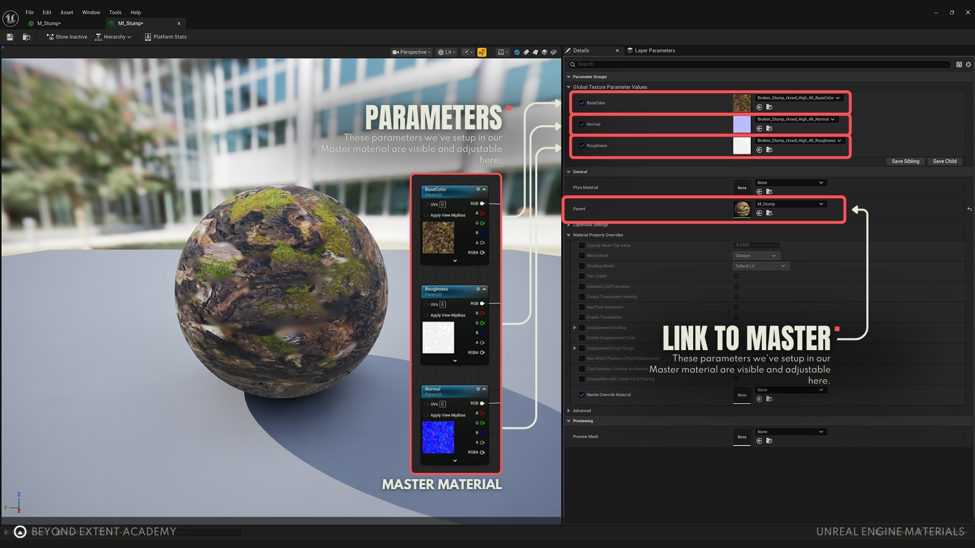
Master Materials
A Master Material in Unreal Engine is a base material setup that acts like a template for many different materials. As we saw in the previous lesson, it features a Material Graph where we can add nodes and create all of the logic and functionality for a material. The idea is to create one universal setup with controls for textures, colors, and values, and expose those values as controllable parameters. Master Materials need to be compiled by the engine into optimized shader code so that the GPU can understand and run them, which is why we want to have as few of them as possible.

Material Instances
A Material Instance is a lightweight “child” of a specific Master Material. You will notice that it doesn’t feature a Material Graph like the Master Material does. Instead, you will see a list with all of the parameters you exposed in the Master Material, and you will be able to quickly adjust them individually. The Material Instance is then applied to your asset.
In short, the process to create a material goes like this:

There are many advantages for using this workflow:
- Speed: Any changes made to Master Materials will need to be recompiled, which can slow down a workflow. Changes made to Material Instances, on the other hand, are instant and don’t require recompilation.
- Organization: One Master Material per use case keeps the project tidy and is easy to keep track of.
- Performance: All instances of a Master Material reference the same compiled shader, reducing GPU load.
- Flexibility: Artists can quickly experiment directly in Material Instances without touching complex graphs.
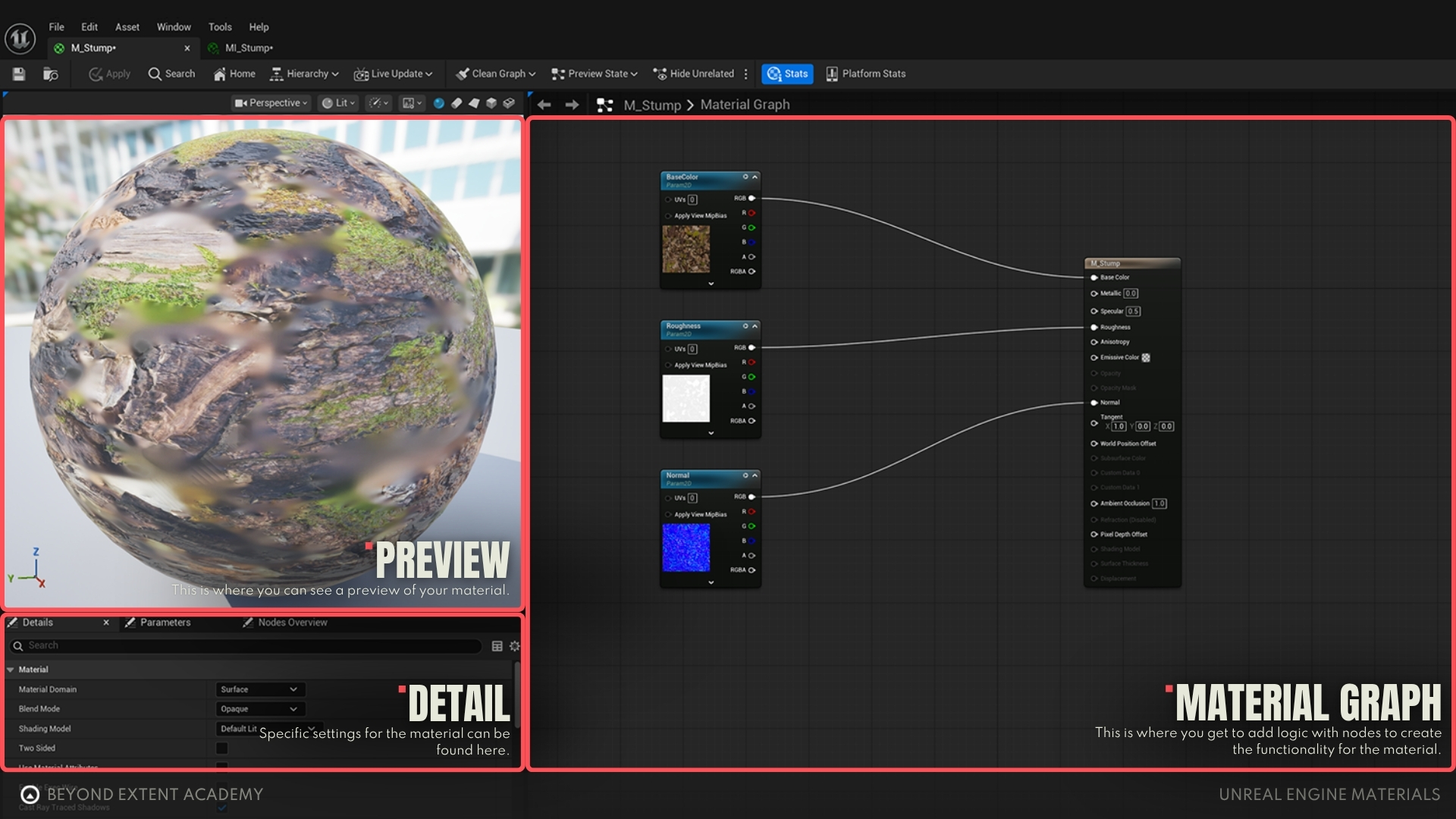
MATERIAL EDITOR
As we’ve already seen, the Material Editor is the main workspace where you build materials. Here you will be adding nodes and connecting them together. Those nodes will perform certain functions and pass along the information until it reaches the final output, which is usually the Result Node that is placed by default in the material graph. Each node and how they’re connected together will influence the properties of your material, like color, roughness and normals, and alter how they will look.
MATERIAL PREVIEW
Inside the Material Editor, you can preview the material you’re making on different shapes (sphere, cube, cylinder, plane). This lets you quickly test how a material behaves across curved vs. flat surfaces, and in different lighting conditions, before applying it to a mesh.
By right-clicking a node and selecting ‘Start Previewing Node’, you will be able to preview the result of your material until that point instead of the Result Node on the preview window.
DETAILS PANEL
The Details Panel shows properties you can adjust related to the node you have selected or to the material itself.

By clicking on an empty part of the material graph or selecting the Result Node, you will find some important settings in the Details Panel, like the following:
Material Domain
The Material Domain tells Unreal how the material will be used:
- Surface: used for most meshes and props, and the domain we will be focusing in this lesson.
- Deferred Decal: used for decals projected onto other surfaces.
- Post Process: used for full screen effects.
- User Interface: used for widget graphics.
Blend Mode
The Blend Mode defines how the material handles transparency. The more commonly used blend modes are:
- Opaque: for solid surfaces like walls or wood.
- Masked: for hard cut-outs using an opacity mask (fences, leaves).
- Translucent: for semi-transparent materials like glass or water.
Transparency has some performance impacts that we will explore better later.
Shading Model
The Shading Model determines how light interacts with the material. When you change Shading Models, you’re switching to different built-in shader variations inside the engine. Each shading model has its own math for how light and color are calculated. The most important ones are:
- Default Lit: used for most surfaces that should react to lighting realistically.
- Unlit: ignores lighting, useful for UI or emissive effects.
- Subsurface: simulates skin, wax, or leaves where light scatters inside.
For the purposes of this introductory lesson, we will focus on this combination of settings:
- Material Domain: Surface
- Blend Mode: Opaque
- Shading Model: Default Lit
A material like this can be used for the majority of props in an environment, as long as they don’t need transparency and should react realistically to lighting.
exercise
Creating your First Parameters

Creating your First Parameters
overview
lesson example content
Get into it instantly by downloading the starter content for this lesson
download lesson contentNODES
Out of the box, Unreal Engine provides many of nodes for you to use in your material. You can access a list of all nodes by right clicking on the Material Graph. There are nodes related to mathematical calculations, textures, blending, and much more. It can be overwhelming at first, butthe majority of nodes are never used. You only need to focus on the nodes you need for your current task. Learn as you go instead of trying to absorb everything at once! There are also multiple ways of achieving similar results by combining different nodes, which you will get familiar with over time.
In order to understand our nodes, we first need to understand some basic math. This will help us manipulate our textures and get more variation out of them.
CONSTANTS AND VECTORS
The most basic nodes you will find yourself frequently using are constant and vector nodes.
A Constant is a single number. They’re used everywhere, usually in combination of some simpler math equations and to set property values. For example, you can connect a Constant node to the Metallic property of the Return Node, and by changing the Constant’s value you can change how metallic your material is, 0 being non-metallic, 1 being fully metallic. Values between 0 and 1 can also define the material’s Roughness, with 0 being fully smooth and 1 fully rough.
A Constant value also represents color. A value of 0 represents the color black and 1 represents white, while shades of gray are represented by values between 0 and 1.
Vectors are a group of values associated to different channels. The values refer to the RGBA color channels or to XYZW coordinates.
- A Vector2 node contains two values. It’s often used to represent XY coordinate values or to control two individual constants in the same node. Can be used for example to scale or offset UVs.
- A Vector3 node contains three values. Usually used to represent positions or directions in the 3D space, with the values associated to the XYZ coordinates or to set colors. For example, a combination of (1, 0, 0) will result in pure red.
Any of those nodes can be turned into parameters that can be controlled in the Material Instance. A couple of details: the Vector2 and Vector3 nodes when converted into a parameter will become a Vector4 parameters, which contain four valeus (RGBA or XYZW). Also, a Constant node turned into a parameter is called a Scalar parameter.
When used with other math nodes, constant and vector nodes can perform a wide variety of calculations.

MATH NODES
Math nodes are small functions inside the Material Editor that let you perform calculations to manipulate numbers, colors, textures, or masks. Those calculations can be as complex as you need them to be.
The most common nodes you will be using are Add, Subtract, Multiply and Divide. Not only they can perform common calculations, but also blend colors just like Blending Modes in Photoshop. Some examples:
Example 01 - Adding a color variation setup
connect a color texture and a Vector3 to an Add node. The color you choose on the Vector3 node will be added to the color texture. Notice how choosing black (0, 0, 0) will have no effect, because you’re effectively adding zero to the other color.

Example 02 - Decreasing intensity of a mask
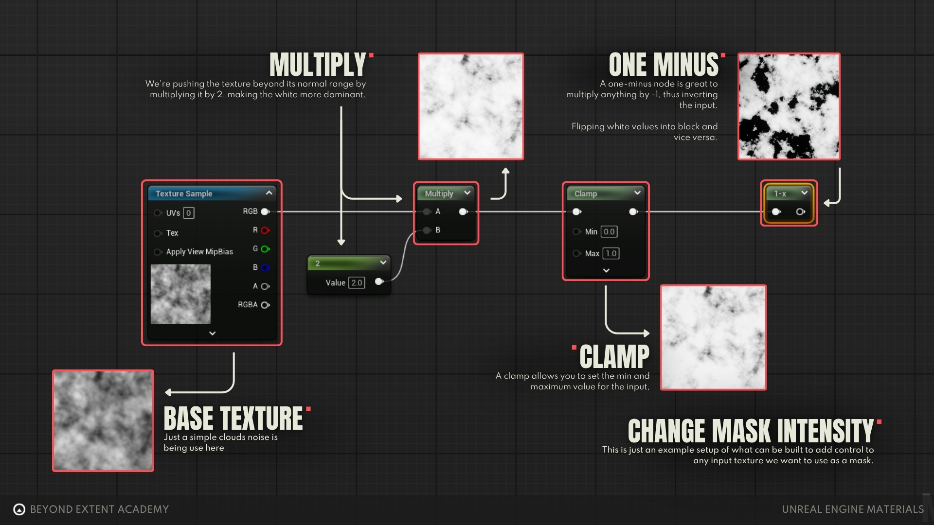
Multiply and other operations can exaggerate values past 0 and 1. You will still end up with black or white but if the result is used in other calculations you might have unpredictable results. If you want to restrict your result between 0-1, you can use a Saturate or a Clamp node after your result. The Saturate node is slightly cheaper and forces the clamp between 0-1, while the Clamp node is more flexible by letting you define the minimum and maximum limits instead.
- Black pixels will stay black. Black is zero, so it will always be zero no matter what is the multiplier.
- White pixels will stay white if the Constant value increases. White is 1, so when multiplied by any value higher than 1 and will stay white, but will go towards black if multiplied by less than 1.
- Gray values will go towards white the more you increase the multiplier and towards black the more you decrease it. For example, a 0.5 gray pixel multiplied by 1.5 will become 0.75 (closer to white). Multiplied by 0.5 it will become 0.25 (closer to black).
- Setting the Constant to 1 will keep the value unchanged, since multiplying a value by 1 results in the same value. Multiply by 0, and the whole mask will become black.
Another useful node for math operations is the OneMinus node. It take an input value and subtracts it from 1 (or 1-input). In practice this inverts any value between 0-1, very useful for inverting masks.
Hotkeys:

exercise
Setting up additional Parameters
Setting up additional Parameters
overview
lesson example content
Get into it instantly by downloading the starter content for this lesson
download lesson contentTEXTURE PACKING
In previous lessons you learned how to pack different black and white maps in different channels of a texture in order to save memory. You will notice that by doing that you also save on texture samples. Instead of having multiple samples, you can have all those textures coming from a single one. This is important because materials are limited to a maximum of 16 texture samples, and the more you have the more complex and expensive a material becomes to render.
When you set out to create a material, it’s important to consider how your textures are packed and create some standards across your project. If you decide that your material will use a specific texture packing, like Metallic on the R channel, Roughness on G and Ambient Occlusion on B, this material and it’s instances will only work properly on assets with this exact packing method. This is an important consideration for your pipeline, to avoid having multiple Master Materials to account for all the different texture packing methods.
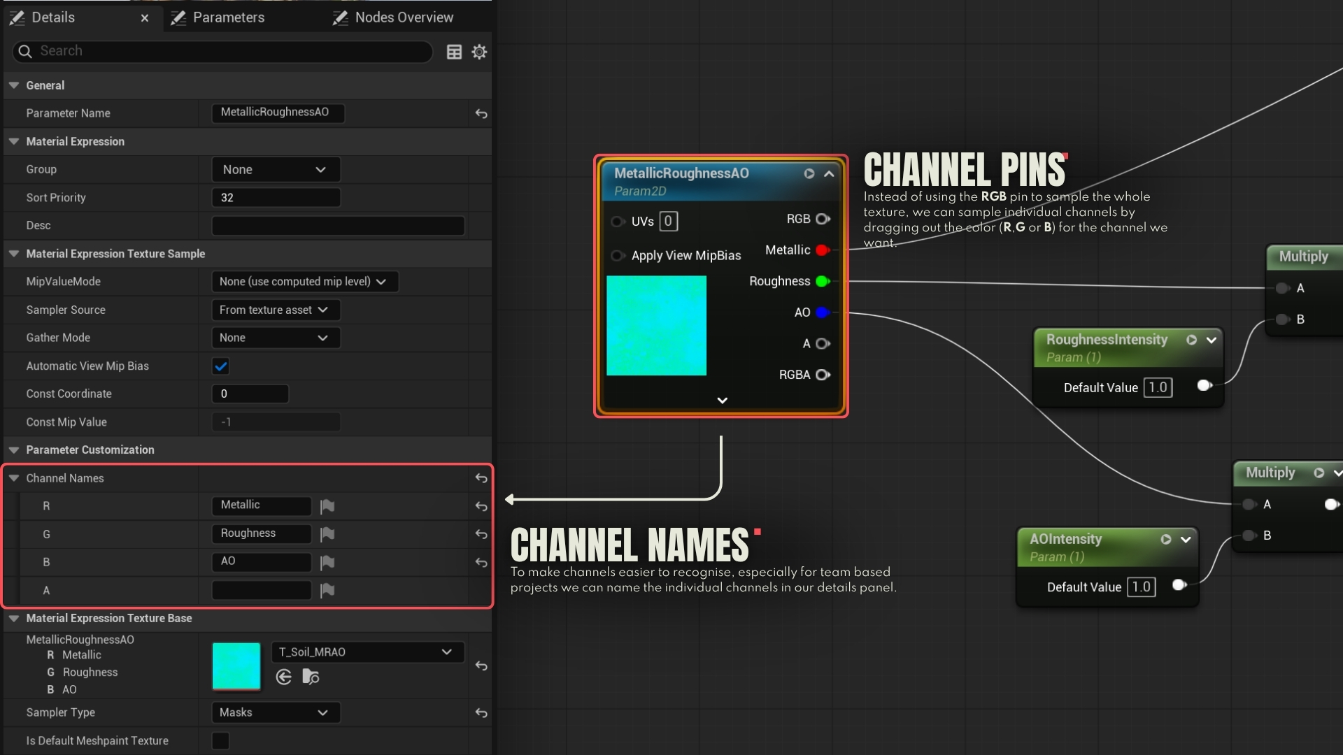
If you have a Metallic, Roughness and AO textures packed together, how will you connect it to your Result Node? It’s very simple. The Texture Sample node has all the channels separated. You can use those channels to isolate the specific map you need and perform your calculations with it, like shown in the example below.
It’s also a good idea to name your packed texture node in a way that it’s easy to tell what is packed in each channel. For example, if you have a Metallic Map on channel R, Roughness on G and Ambient Occlusion on B, you can name your texture sample parameter as MRAO or literally the name of the properties, like MetallicRoughnessAO. In the details panel of this node, under ‘Channel Names’ you can also define names for each individual channel, making it even clearer.
MANIPULATING UVS
As you already know, UVs are 2D coordinates ****(U = X axis, V = Y axis) that tell the engine how to map a flat texture onto a 3D surface. We can add some math to our materials to manipulate the UVs in case, for example, we want to tweak the texture offset and material tiling of a tileable material. This is the setup we’ll make, while we also learning about a few new nodes.
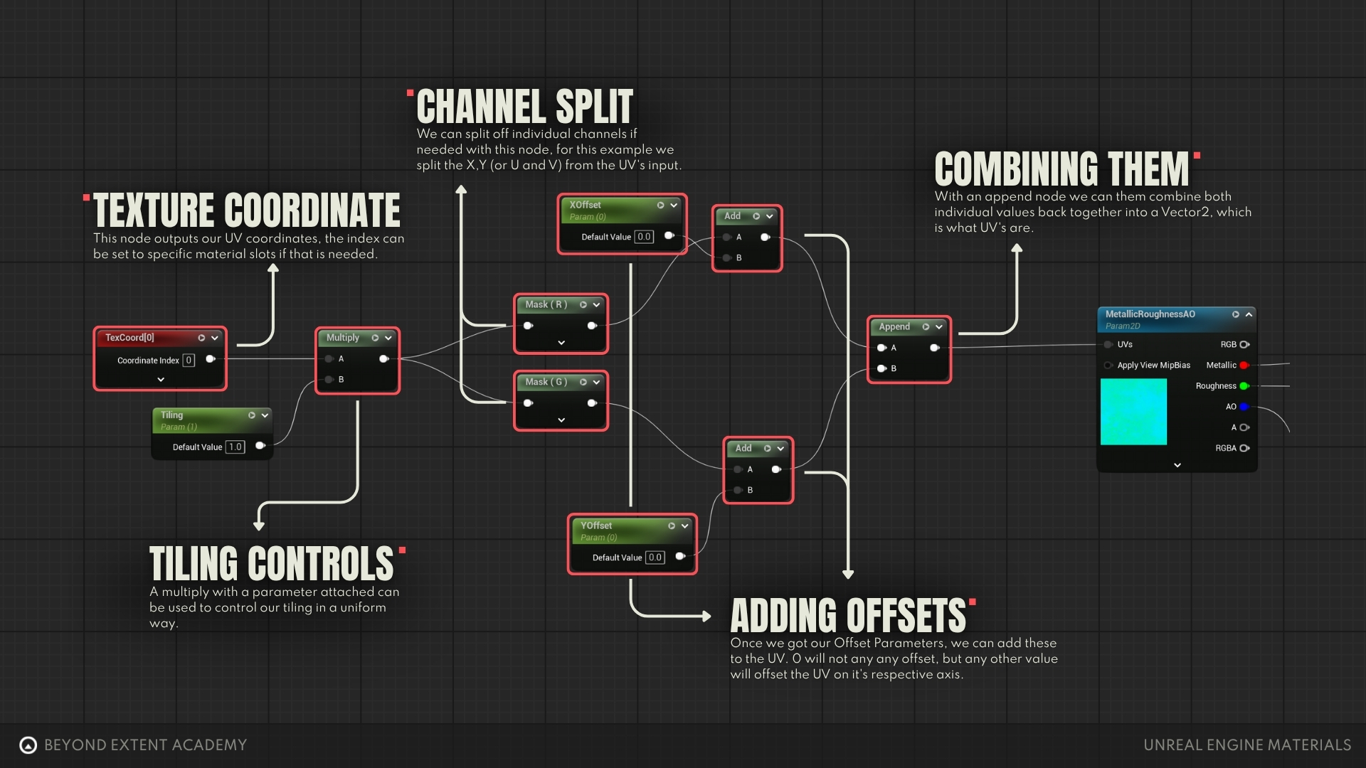
- The ‘Texture Coordinate’ node (shortcut: hold ‘U’ + left-click) outputs UV coordinates with two vectors (X and Y). The ‘Coordinate Index’ can be changed in case you want to create a material that supports multiple UV channels.
- To control the tiling of our material, we can connect the Texture Coordinate to a Multiply node and add a parameter called ‘Tiling’.
- We can split the X and Y channels of our Texture Coordinate if we want to manipulate them individually. For that we can use the ‘Mask’ node. In this case, we want to tell one of the Mask nodes to isolate the R channel and another Mask node to isolate the G channel (remember that R and G are equivalent of X and Y). You can do that in the details panel or by expanding the arrow on the bottom of the Mask node and checking the boxes related to those channels.
- If we now connect each Mask node to a different Add node plus a parameter (XOffset and YOffset), we will now be able to control the X and Y texture offsets independently.
- Now we need to recombine the two channels back into a double vector. We can use the ‘Append’ node for that. The A input will be the first value (X) and the B input will be the second value (Y). Note: If you ever wanted to assemble a third vector, you’d just have to add another Append node after this one and connect a value to the B input, which would create the third channel (Z).
- With our assembled texture coordinates, we can now connect it to all the ‘UVs’ inputs on our texture samples.
You can now adjust the tiling and offset of your material in the material instance!
ORGANIZING YOUR GRAPH
As your materials become more complex and your Material Graph becomes a spaghetti wall, there are some features and nodes we can use to make the graph easier to read and more organized.
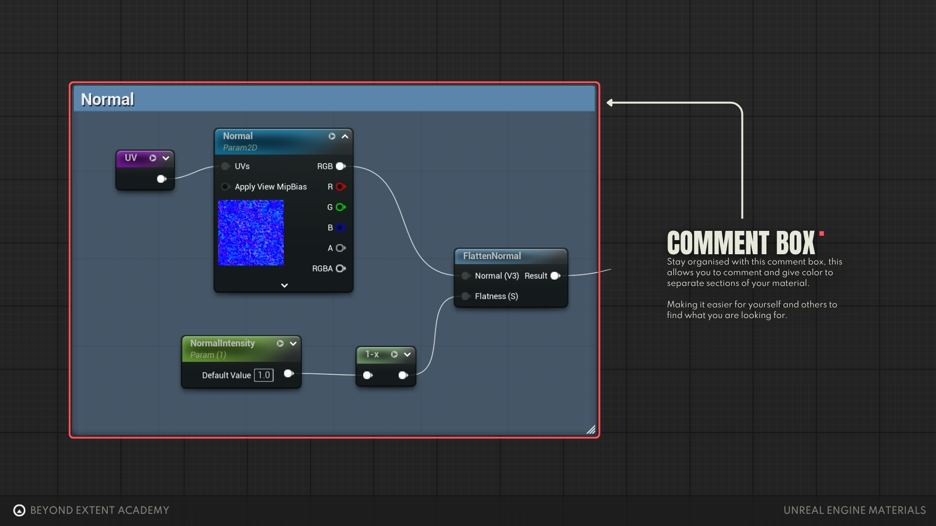
COMMENT
By selecting a group of nodes and pressing ‘C’, nodes will be encompassed by a comment box. You can give it a title, change its color and move the comment box around with all of the nodes inside. This is great to keep chunks of nodes separated and organized.
DESCRIPTIONS AND GROUPS
Parameter nodes have a ‘Description’ property in the details panel. You can describe there how this node is intended to be used, like the order of channels in a packed texture or which values to set for the desired effect. The description can be read in the Material Instance by hovering the cursor on the parameter.
When you start to create many parameters, you’ll notice that they will start to build up in your material instances suddenly you’ll have a long and messy list of parameters. To avoid this, you can group nodes together inside their own categories. To do so, select a parameter and in the details panel change the Group from ‘None’ to whatever you want. This will create a group with a name that you can assign to any other parameter as well. You can also change the Sort Priority to organize them in the order you prefer.
Notice in the example below that the NormalIntensity node’s description is set as “This node controls the normal intensity”. It was also assigned to the created group ‘MaterialParameters’, along with other parameters, and with Sort Priority 5.
In the material instance, you can see that my parameters are organized inside the MaterialParameters group. The NormalIntensity is on the position 6 because the Sort Priority starts counting from 0. Hovering the cursor over it will also show the description.

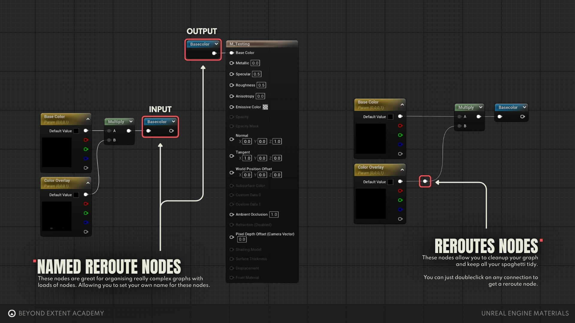
REROUTE NODES
By double-clicking on a node connection, you can add a Reroute node. You can move them around to organize better your node connections, as well as pulling out multiple connections out of it. It’s great to avoid lots of crisscrossing wires. You can see in the image a couple of examples after the MRAO nodes.
The Named Reroute is a node that can have a name and color and acts like a portal, receiving an input and letting you reuse this result anywhere else in the graph without long wires crossing all over the place. It simply receives a value and outputs it somewhere else. After creating a Named Reroute node, you can search in the nodes list for its name and create as many copies as you need. In the example you can see that the UV result is connected to a purple reroute node named ‘UV’ and copies of this node are added next to each texture sample instead of dragging multiple wires from that single point. There’s another reroute after the BaseColor so it can be connected to the Emissive and also brought to the Result Node.
Our graph is still pretty simple, but the more complex it becomes the better it is to keep it organized and easy to read, and it’s where those organizing tips really make a difference.
COPY/PASTE NODE DATA
If you want to easily see directly the results of the previous exercises, you can open the .txt file linked below, copy the whole code and paste it into your material graph. It will generate most nodes and connections for you.
IntroToMaterials_NodeGraphCode.txt
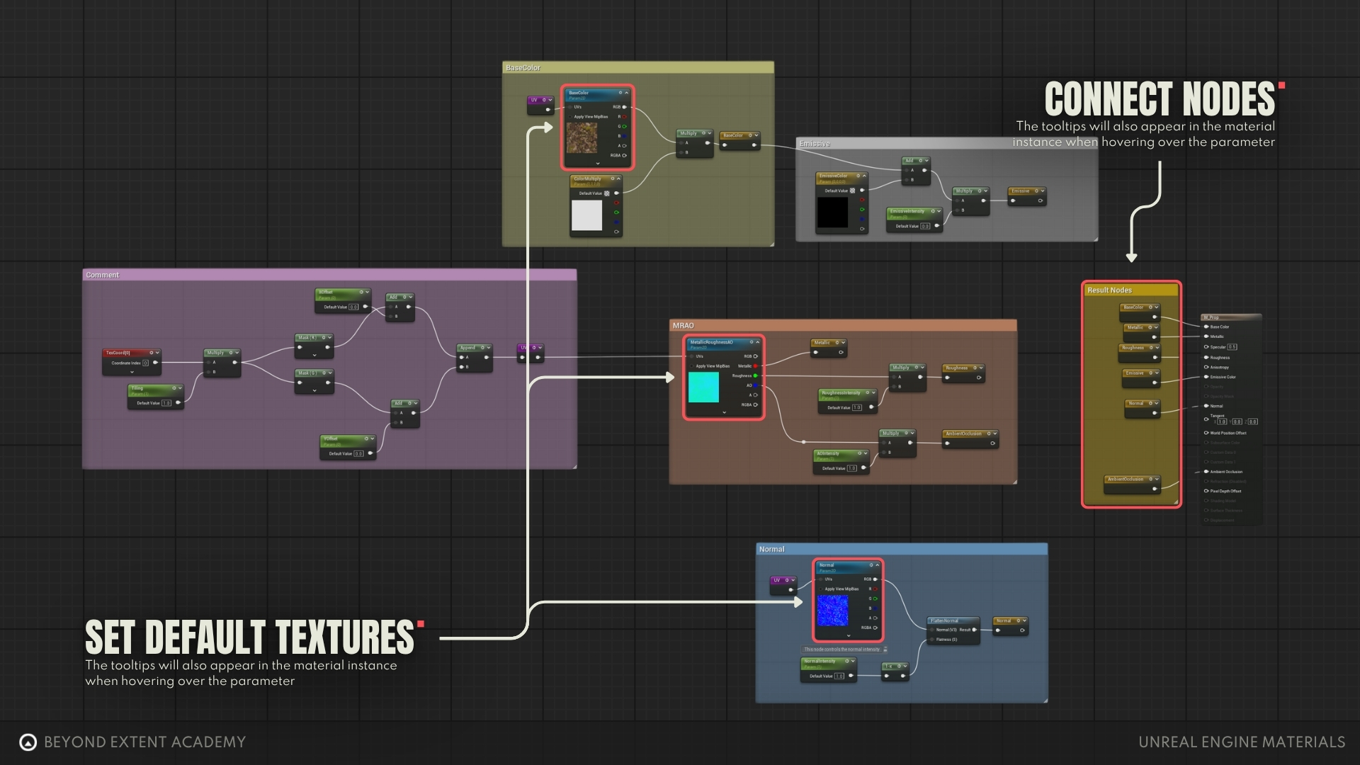
You will notice that the final connections to the Result Node and the textures in the Texture Sample nodes are missing. To fix that:
1- Connect all the yellow nodes inside the Result Nodes comment box to their respective inputs on the Result Node.
2- Click on each Texture Sample and assign a default texture to them that matches their compression type (Color, Masks, Normal).
This is a good example of how you can copy chunks of material nodes, blueprint nodes and even actors from your project to a text file to then paste it back in Unreal. Although you might lose some data in the process (like the textures and some node connections), it can be useful for sharing small snippets of data with other people or between projects.
CONCLUSION
In this lesson, you learned the foundations of Unreal’s material system, from the interface of the Material Editor to the difference between Master Materials and Material Instances. You now know how to expose parameters, create calculations, organize graphs, and build flexible materials that can be quickly reused across assets. This is just the beginning! In future lessons, we’ll expand into more advanced techniques, including material blending for complex surfaces, layered materials for modular workflows, and other types of materials used for translucent assets, foliage and decals.